
|
||||||
| Site Map | ||||||
|
|
||||||
|
|
||||||
| What is PoweredUSB? | Retail and PoweredUSB | Industry and PoweredUSB | Parts of PoweredUSB |
|
|
| USB Standards | Contact Us | Other Links | FAQs | |||
|
Overview
What is PoweredUSB? PoweredUSB provides a single cable connection that supplies both the standard USB communication signals and two additional wire pairs for extra power. The design of PoweredUSB and it’s connectors allow for hot-plugging. This combined with Plug-and-Play operating systems allows PoweredUSB to be easily maintained and supported in the retail environment. One of the limitations of standard USB is the amount of +5V current available to supply attached peripherals. Normally, 500mA is available at each host port and each powered external hub port. This amount of current is sufficient for most PC type peripherals like mice and keyboards. When the power requirements exceed the 500mA limitation, external peripherals require the use of an external power supply (brick) to supply the necessary power requirements. This limitation takes away from the true "Plug-and-Play" idea conceived for USB peripherals. The original design of PoweredUSB implementation was a joint effort between IBM and FCI/Berg specifically for IBM retail point-of-sale terminal. While the original understanding is that the connectors and its implementation was going to be unencumbered, IBM was issued a patent on the connection scheme. Read more about IBM's patent. PoweredUSB components consist of the following:
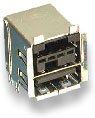
1. Host-side PCB Connector
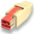
2. Host-side Cable-end Plug
3. PoweredUSB Cable, Bulk There are several manufactures of PoweredUSB cables that are USB 1.1 compliant but only one supplied by CyberData Corporation has been found to be USB 2.0 compliant. Just because a cable constructed seems to function, it may have data loss that is not perceived by the user. It is recommended that purchasers of PoweredUSB cables ask the supplier to confirm USB 1.1 or 2.0 compliance not just a functional test.
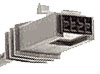
4. Peripheral-side Cable-end Plug
The PoweredUSB specification says: "Peripheral side connectors are at the discretion of the manufacture as long as they meet good engineering practices and as long as this connector is not a Host type."
Hot-Plugging/Hot-Unplugging Considerations The PoweredUSB connector is not rated to withstand any specific number of arcs which may occur during hot-plugging or hot-unplugging. Since equipment users will associate USB with hot-plugging and hot-unplugging, it is recommended that devices be designed to avoid connector degradation or electronic component failure that could occur if contact arcing is not suppressed. PoweredUSB ground pins make contact before V+. This feature allows for suppression of contact arcing to be designed into the connector. Peripheral-side connectors that do not incorporate ground first mating may damage the connector or PoweredUSB device by electrical arcing during insertion. (As of April 2006, only Conquest Technology provides a Series "B" staggered pin 1x8 peripheral side PCB connector. PoweredUSB.org has been informed that a Series "B" 2x4 peripheral side PCB connector will be released shortly that also supports hot-plugging with staggered pins.) Electrical Specifications |
[Home] [What is PoweredUSB] [PoweredUSB in Retail] [PoweredUSB in Industry] [PoweredUSB Parts] [USB Standards] [Contact US] [Other Links] [FAQs] [Site Map] |